In this article in our BACnet Basics Series, we look at Device Profiles, why they’re important and how they’re created. We’ve also included a real world example that illustrates how to use device profiles to accurately specify your own projects.
What are Device Profiles?
As we saw in BACnet Basics: What are BIBBs?, device functions come in five basic categories, each containing specific capabilities. For example, the category Data Sharing (DS) includes capabilities like Read Properties (RP), Write Properties (WP) or Change of Value (COV). If we combined all these services into a minimum collection of capabilities, we would be creating a device profile.
As an analogy, think of the profile “Automobile”. Every machine that claims to be an “automobile” needs the functions of Acceleration (A), Deceleration (D) and Maneuverability (M). Of course, there can be automobiles that do much more, but every “automobile” must, at minimum, perform these three functions (A,D,M).
Definition: BACnet device profiles define the minimum set of BACnet Interoperability Building Blocks (BIBBs) supported by a device claiming that profile. When a device claims a specific profile, you know that it contains a preset of specified functions and services. Profiles are handy because they provide a short-hand method for describing a device and its interoperability capabilities. Device profiles are organized into Groups and Families
Device Groups
Device Groups are general categories of device functions. There are four Group types:
Operator Interface—Covers the minimum capabilities for workstations and other user interface devices. Devices normally support A-side (Client) functionality.
Controller Device—Covers anything from programmable building controllers to smart sensors. Devices normally support B-side (Server) functionality, but more advanced supervisory controllers also include A-side (Client) functionality.
Control Station—Covers lighting control stations that are smaller client devices that support specific user controls such as manual light switches.
Basic Device—Covers all “miscellaneous” family functionality. Usually included alongside other device profiles.
Device Families
Each Profile Group contains various Families within it. Families cover profiles for various, supported building systems like Lighting, Life Safety, and General Purpose. For example, the Controller Device Group contains profiles for the following Family types:
(Example) Controller Family
General Purpose—General purpose controllers usually for HVAC and lighting.
Access Control—Access control controllers such as an access control panel
Lighting—Lighting controllers such as supervisory lighting controller
Life Safety—Life safety controllers such as a fire detection panel.
Elevator—Elevator controllers
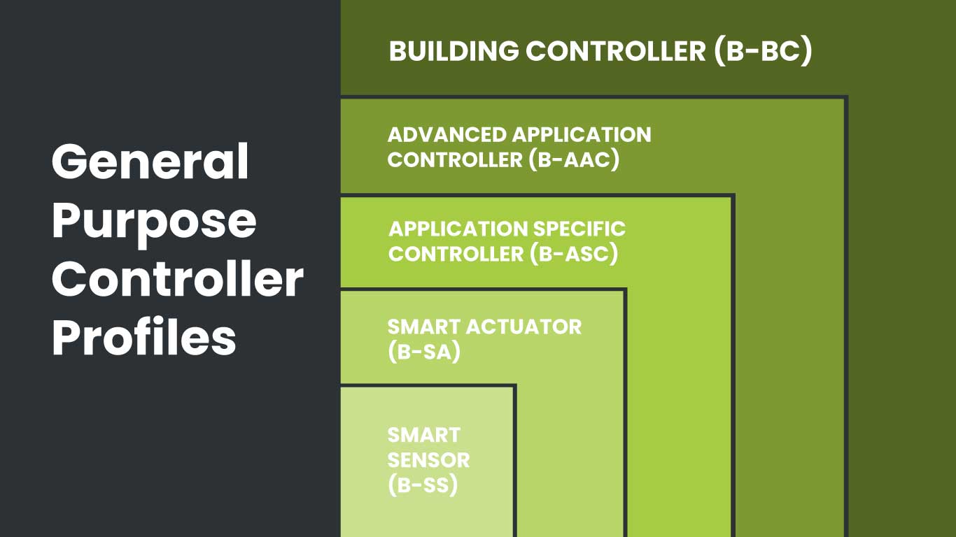
Let’s zoom into the General Purpose profile family within the Controller Device Group and see what BIBBs it contains.
Building Controller (B-BC) —Field programmable and configurable supervisory controllers in HVAC and general purpose application.
Advanced Application Controller (B-AAC)—Controllers that run advanced HVAC or general purpose control applications.
Application Specific Controller (B-ASC)—Controllers that run specific HVAC or general purpose control applications.
Smart Sensor (B-SS)—Small sensors that provide sensor values to other devices.
BACnet device profile Families are organized in a container hierarchy. As you move up in complexity, you increase the minimum amount of BIBBS required. Like nesting dolls, each profile contains all the minimum profiles from the previous ones.
For example, the above General Purpose BACnet profiles increase in complexity as you move up from Smart Sensor to Building Controller. All BIBBS included in a Smart Sensor profile are always included in a Smart Actuator profile, and all the BIBBs included in those two profiles are always included in an Application Specific Controller, and so on.
Although higher level BACnet profiles contain more BIBBs, it’s not the number of profiles that matters. Each profile requires a minimum number and type of profiles. So, even if a device contains or exceeds the minimum number of BIBBs, it doesn’t guarantee it will meet the standard. It must contain the minimum number of the correct BIBBs to meet the profile standard.
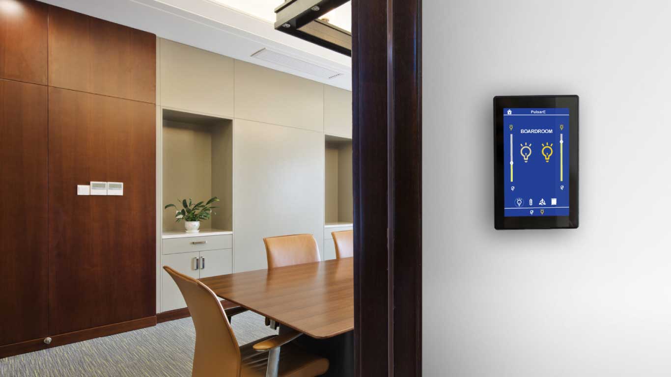
Specifying Device Profiles: Boardroom Example
Let’s use the Device Profile Quick Reference Guide to see an example of how to choose the device profiles for a real-world project. Read the following scenario:
You want to outfit a medium-sized boardroom equipped with a control panel with a built-in controller. The panel will control the room’s temperature and lighting. You also need manual lighting controls near the door.
To determine the device profiles needed for the project, we can start by listing the functionality we need. We will need HVAC controls for temperature. For lighting, we will need controls for both the panel and a manual user control switch on the wall. Therefore, we will need functionality from the Controller Group and Control Station Group.
Next, we can determine what Families we need within each group.
For the Controller Group, we need:
General PurposeFamily for HVAC
Lighting Family for panel control lighting
Access ControlFamily for access
For the Control Station Group, we need:
Lighting Family for manual switch lighting control
Finally, we can choose specific profiles to fulfill our HVAC and lighting functionality.
HVAC Profiles
In the Reference Guide, we see the following profiles for the General Purpose Controller Family:
B-BC: The building controller is intended for field programmable and configurable supervisory controllers in HVAC and general purpose applications.
B-AAC: The advanced application controller is intended for controllers that run advanced HVAC or general purpose control applications. It does not require being configurable through BACnet.
B-ASC: The application specific controller is intended for controllers that run specific HVAC or general purpose control applications. It does not require being configurable through BACnet.
B-SA: The smart actuator is intended for small actuator devices that allow being commanded.
B-SS: The smart sensor is intended for small sensor devices that provide sensor values to other devices.
We can ignore the last two profiles, because we need neither actuators (B-SA) or sensors (B-SS) for the project. We can also eliminate the Building Controller (B-BC) profile because it does not require supervisory control. Depending on our HVAC needs, we could choose either the Advanced Application (B-AAC) or the Application Specific (B-ASC) profile.
Lighting Profiles
In the Reference Guide, we see the following profiles for the Lighting Controller Family:
B-LS: The lighting supervisory controller is intended for controllers in lighting applications that can command and operate subordinate lighting controllers, in particular through group write commanding.
B-LD: The lighting device is intended for lighting controllers that control individual lights or groups of lights. Normally used as leaf nodes in lighting group setups.
We would choose the B-LD profile if the panel only controls one group of lights. However, if the lighting is more complex, we might opt for the B-LS with supervisory controls.
Control Station Profiles
Because the room also requires manual user lighting controls, we need a profile from the Control Station Family. In the Reference Guide, we see the following profiles:
B-ALCS: The advanced lighting control station is intended for sophisticated control stations that support user view, control and limited configuration of lighting functionality. Provides full commanding support of lighting objects and group operations for them.
B-LCS: The lighting control station is intended for control stations that support simple control of lighting functionality and limited status indication. Provides limited support of commanding lighting objects.
The simpler B-LCS would work for this project. But, again, depending on the complexity of the room’s lighting, we might choose the more complex profile.
Conclusion
Through the Boardroom Example above, we can see how BACnet profiles make project specifications easier and more accurate. Standards and profiles support an accurate procurement process, requiring less change orders and adjustments. Defining capabilities also creates an outcomes-based workflow so that buildings function the way owners and tenants need them to.
Every complex topic or field needs a helpful naming system. Scientists name flora and fauna by genus and species. Even astronomers have their own planetary nomenclature. Standard naming conventions do just that—they standardize how we talk about things. They’re also a convenient way to condense large amounts of information into a short form. Hence, they function like acronyms. We needn’t sound out “self-contained underwater breathing apparatus” when we can simply utter S.C.U.B.A. right?
In building automation, the same need for standards and compression applies, and BACnet gives us a convenient way to describe the functionality of devices using something called BIBBs.
What are BIBBs?
Definition: BIBBs stands for “BACnet Interoperability Building Blocks” and is a standard naming convention for representing specific device capabilities using simple acronyms. That is, it creates simple categories to describe how one device works with another.
Without short-form descriptions, listing all the capabilities and services that a device offers would turn functional descriptions into a messy scrawl of technical jargon. By condensing these functions into acronyms, BIBBs makes it easier for FMs, system integrators, and building engineers to talk about the same things. BIBBs help buyers get the minimum number of services for the job without over-engineering and spending for extraneous functionality.
BIBB Categories
The BIBB naming system starts with five broad categories that list interoperability functions. These are high level functions that host specific capabilities within them. Categories include:
Data Sharing (DS)
The data sharing function describes how devices exchange data. Data sharing is essential for reading and writing data from one device to another. For example. If you wanted to regularly check the water temp of your boiler to monitor its performance, you would need the DS functionality.
Alarm & Event Management (AE)
The alarm and event management functionality is for detecting and notifying alarms and events. For example, if your boiler temps exceeded a specified setpoint, the AE function would allow you to receive an alert.
Scheduling (SCHED)
The scheduling functionality is for scheduling values based on date, time, and calendar. For example, if you wanted to schedule your boiler to provide after-hours heating for tenants.
Trending (T)
The trending functionality is for trend logging and historical data support. For example, if you wanted to store your boiler’s temp data to create a history for your engineer.
Device Management/Network Management (DM/NM)
The DM/NM is for setting up device and network management. It allows devices to discover each other, to synchronize clocks, and to reset a device to factory settings (reinitialize). For example, if you wanted to discover a newly installed boiler temp sensor.
Specific Capabilities
Specific capabilities, or sometimes called services, are distinct functions that exist within a BIBBs category. Capabilities also have acronyms. For example, the Read Property (RP) service is under the data sharing (DS) category. The service must exist for data sharing to occur. That is, a device (e.g., controller) must be able to read data, while another device (e.g., thermostat) must be able to send it. Many devices have both capabilities. Here are some examples of services for different BIBBs categories:
Data Sharing (DS)
Read Property Multiple (RPM)
Write Property (WP)
Change of Value (COV)
Alarm & Event Management (AE)
Notification (N)
Alarm Summary (ASUM)
View Notifications (VN)
Device and Network Management
Dynamic Device Binding (DDB)
Text Message (TM)
Reinitialize Device (RD)
Find a more extensive list of device capabilities here.
Clients and Servers
BIBBs also distinguishes between clients and servers, assigning and A and B category to each respectively. Client devices (A) can initiate or call for data or service from a device that can respond to that request (B). An example of this would be a controller (A) requesting temp data from a thermostat (B), which responds with the requested data. You can remember this order by recalling that the letter “A” comes before “B” in the alphabet, just as a request must precede a response.
Putting It All Together
Now that we have all three parts of BIBBs, let’s look at a full interoperability description. The BIBBs naming syntax places the category first, specific capability second, and server/client designation third. Each acronym is separated by a dash. Consider a BACnet controller that has data sharing (DS), a read property service (RP), and client capability (A). It would be designated as DS-RP-A. Can you guess what functionality a thermostat would require to send temp data back to the controller? If you answered DS-RP-B, you’re correct!
Conclusion
As we’ve seen, BIBBs are the “building blocks” of the standardized system of naming devices and their interoperability functions. Devices can have many different functions, so there’s also a need to group them. For example, controllers, sensors, and actuators must all have a minimum number of specific functions to work. These groups of functions are called BACnet device profiles. Like BIBBs acronyms, profiles give us a shorthand way of quickly designating and describing a device. Read BACnet Basics: What are Device Profiles? to learn more or visit The BACnet Institute for free training.
If you have commercial tenants, they’ve likely scheduled heating or air conditioning outside of your building’s usual business hours. Managers and owners commonly refer to these extra hours as overtime HVAC, after-hours HVAC, after-hours air conditioning or some variation. These overtime utility services give companies the flexibility to host special events, hold annual meetings, or simply extend their workday hours.
Tenant overtime HVAC systems are online platforms that automate the scheduling and billing of those after-hours HVAC requests. These systems streamline much of the traditional steps of a tenant overtime program, including scheduling and billing. Consequently, they save property managers and their staff time and resources. In addition, overtime HVAC systems can increase tenant satisfaction and conserve energy. Modern systems operate on a software-as-a-service model (SaaS) where property managers pay a monthly subscription for the service, but one-time fees are also available.
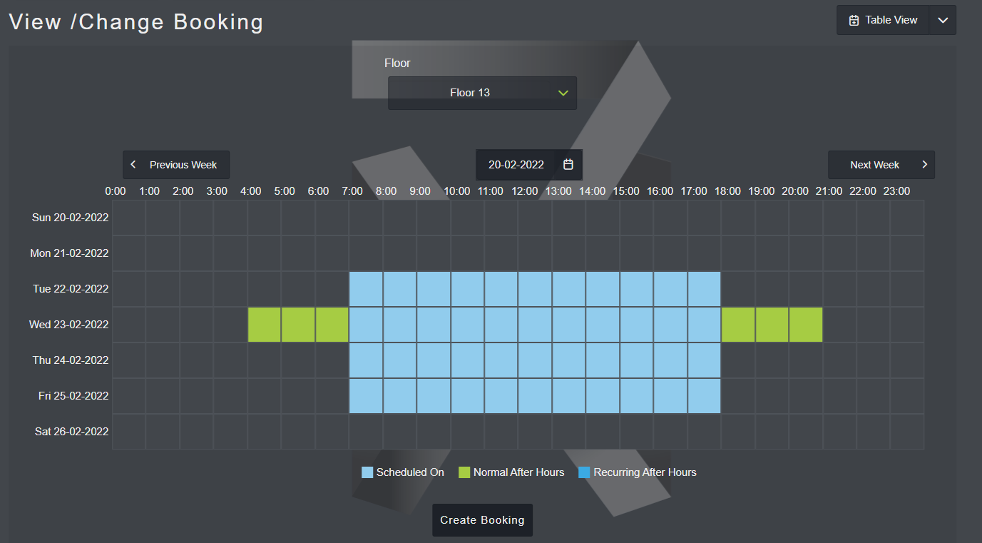
Modern tenant overtime systems let property owners set normal business hours (blue), while tenants can schedule HVAC service outside these times (green).
After-Hours vs Standard Occupancy Times
Standard business hours or “occupancy times” for buildings vary by region, but most fall somewhere around 8 a.m. and 6 p.m. Monday to Friday. Owners and managers define their business hours within commercial leases and agree to provide heating, cooling and lighting for tenants to operate their businesses. However, many leases also allow for “after-hours” or “overtime” HVAC requests. These are defined as any times outside normal business hours, and they’re usually billed separately from normal OPEX.
To recoup the costs for providing after-hours HVAC services, managers and owners usually charge tenants a fixed hourly rate (ex: $35/hour). The rate usually includes an estimated energy cost for providing service for one hour, plus an admin fee to cover staff time.
Overtime HVAC Scheduling
Because after-hours HVAC requests are outside standard operating hours, tenants must schedule them with the manager or building engineer. Typical steps in a standard overtime program usually involve the following:
The tenant makes an overtime HVAC request via email or text.
The manager records the request in a spreadsheet and notifies the building engineer.
The engineer programs the request into the building’s BMS.
The manager invoices the tenant at the end of the month for the overtime charges.
Managing this process requires time and resources, which is why most leases require a 24 or 48-hour notice per request. The window gives staff enough time to schedule the request, but places limits on how spontaneous tenants can be with last minute schedules.
Tenant overtime HVAC systems eliminate or simplify many of the above steps. Instead of an email or phone call, tenants use an online portal and web browser to submit overtime requests. Since overtime systems link to your building’s BMS, they bypass the need for manual reporting and system programming—no managers or engineers needed. This keeps notice times shorter, and tenants benefit from the increased flexibility.
Overtime HVAC systems also come with mobile apps. Tenants use these programs to schedule after-hours services from their smartphones or tablets. The freedom of mobile scheduling tends to increase overall tenant satisfaction with a property’s after-hours program.
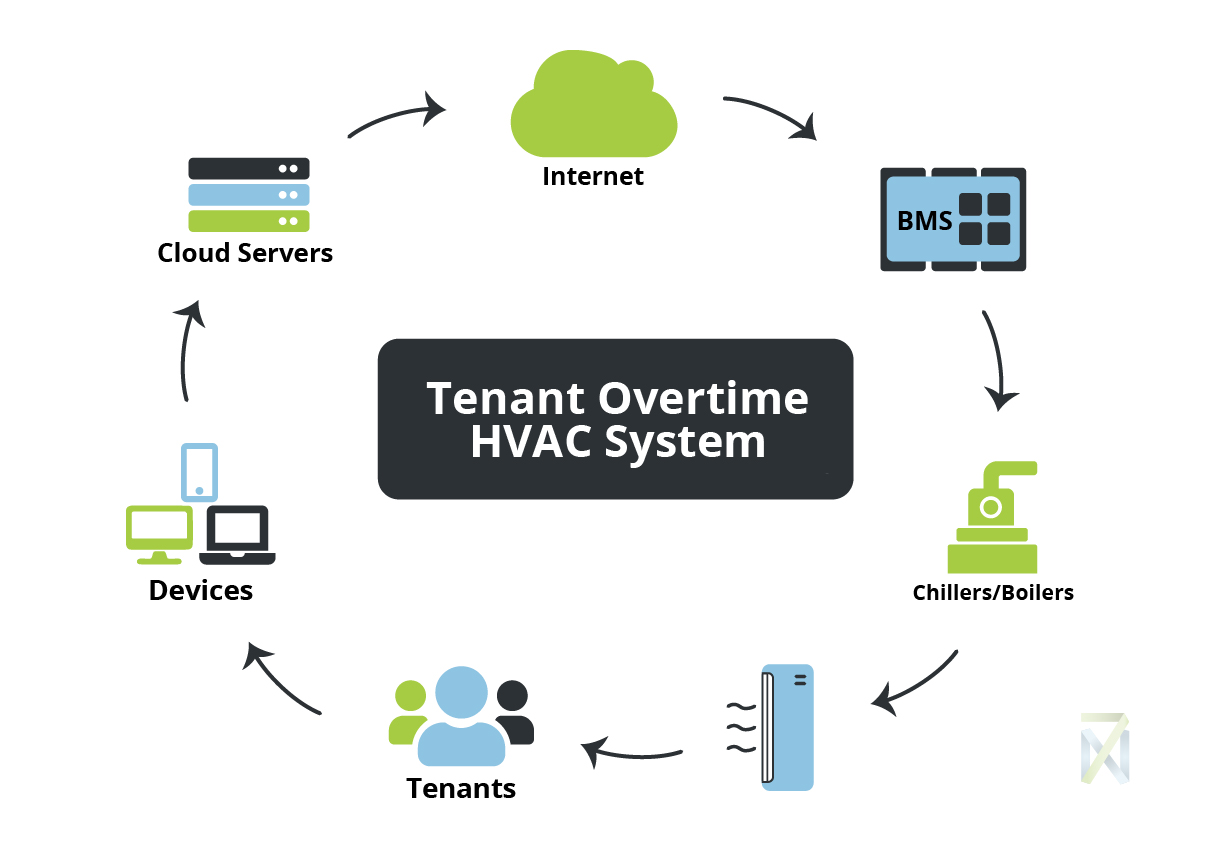
Common connection flow of a cloud-based tenant overtime HVAC system to a commercial property.
Overtime HVAC Billing
Billing for standard hour energy is straightforward. Tenants pay pro rata based on the building’s total utility costs for the month. The strategy essentially splits the energy costs among all tenants equally, and everyone pays their share at the end of the month. However, overtime HVAC charges add complexity to monthly billing. It would be unfair to split overtime energy costs among all tenants, since only specific ones use it, so landlords invoice tenants only for the kWh they use.
However, individual invoicing takes more time. Spreadsheets need updated. Invoices generated. Emails sent to tenants. Plus, manual entry increases the risk of mistakes, leaving tenants paying too much or too little. Tenant overtime HVAC systems automate most of these monthly billing tasks, eliminating human error and tenant disputes around charges.
Overtime systems record BMS operation histories in their servers. So, times, days, and durations of overtime services are automatically generated for any timeframe. Most platforms also automate monthly billing to tenants. Since the system tracks individual usage, it can email automated invoices to tenants, taking the paperwork off property managers.
Energy Conservation
On average, 30% of the energy used in commercial buildings is wasted. After-hour scheduling changes and cancellations happen. It’s not uncommon for tenants to walk into unheated boardrooms or for entire building floors to sit unoccupied while chillers run at full power. Such scheduling mistakes waste energy and money. The bulk of these issues stem from recording mistakes and human error. A work order was overlooked, an email went to spam. Someone was out sick. These are common, often unavoidable, situations.
Because they’re automated systems, tenant overtime platforms eliminate human error. Schedule changes and cancellations are caught more frequently and wasted energy reduced.
Overtime HVAC systems can also positively affect tenant attitudes toward energy waste. Because tenants pay for the overtime kilowatts they use, they’re more cautious about waste. In contrast, attitudes towards energy use during standard business hours can be markedly different. Those tenants often have a “use it or lose it” approach, feeling they should condition the air in their spaces, whether they’re empty or occupied. The attitude is “We’re paying for it anyway.”
Tenant Satisfaction
Aside from time and money savings, the biggest selling point of overtime HVAC systems is their value to tenant businesses. With HVAC scheduling, office managers can operate hybrid workspaces more effectively. Government agencies can use after-hours reports to report on sustainability goals. Software developers could employ overtime usage to evaluate team productivity. Marketing agencies could add overtime energy costs as a billable line item for clients. The value of tenant overtime HVAC systems is yet to be fully realized, but the heart of it lies in their ability to empower tenants to run better businesses and organisations.
Fire protection systems are one of the most complex and ubiquitous structures within facilities today. They contain many parts intertwined with other building components. For example, emergency lighting and smoke detectors wire into your electrical system. Fire pumps and hydrants hook up to your water mains. Fire alarms connect to your building’s access system to automatically unlock exterior doors.
Your HVAC system is also closely coupled to your fire protection equipment, and its maintenance and condition can directly impact the safety of your inhabitants and the extent of damage to your property.
1. Ductwork
Your system’s ductwork distributes conditioned air throughout the building. But during a fire, such distribution is unwanted. As temps rise and smoke builds, your HVAC’s return ductwork can carry smoke, toxic gases, and superheated air throughout other areas. This spreads the fire and puts occupants in danger. Even worse, supply side ductwork can actually “feed” a localised fire with fresh oxygen, increasing the temperature and property damage.
During a fire, smoke is the number one killer. In fact, most fire deaths are not caused by burns, but by smoke inhalation. Therefore, controlling its spread is safety 101. Plus, smoke can often emit from sources besides an open flame. Burnt toast or microwave popcorn could result in smoke rolling through an entire office floor. This could cause a panic and dangerous stampede to exits. So, any fire safety plan should also include the perception of fire itself as a real threat to life and property.
Duct smoke detectors can help. These devices reside within your ductwork where they detect smoke moving throughout your HVAC system and initiate pre-programmed actions. For example, one of your HVAC fan motors overheats and produces smoke. Once activated, the duct detector could turn on an exhaust fan, close a damper, shut down automation systems, signal an alarm and/or cut power to the fan motor itself.
2. Fire and Smoke Dampers
Fire dampers are another critical way your HVAC systems aid your facility’s fire protection system. Dampers are essentially air valves that shut off airflow in the event of a fire. They’re normally installed at any point where your system’s ductwork passes through a wall, floor or other fire-rated partition. The idea is to close off HVAC ventilation for any area where a fire exists. So, locating them within a fire-rated wall, for example, retains the integrity of the wall even if the ductwork falls away or is damaged by fire.
There are two basic types of dampers: fire and smoke. Fire dampers are usually triggered by a physical device such as a fusible link. Once the temperature rises above a specific point, the fusible link will melt and trigger the closing of the fire damper. As its name suggests, the damper’s main function is to stop fire from spreading through the ductwork.
Smoke dampers are part of the smoke suppression system. They typically connect to fire alarm systems, which trigger the dampers to close and prevent smoke transference. There are smoke/fire combination dampers as well.
Most fire codes require fire and smoke dampers to be actuated and tested every few years, depending on the facility type. Make sure you know your fire code and test that your dampers are physically working, installations are compliant and any replacements are compatible with your system.
3. AHU Support and Location
In the event of a fire, your alarm system should shut down any air handling units (AHUs) within the affected area or site wide. Again, the purpose is to contain the movement of smoke and air, and your AHU is the central place where this happens. However, operation isn’t the only consideration.
AHUs are large, heavy pieces of equipment weighing several tons depending on the size of the system. They’re also loud; that’s why they’re usually located within mechanical rooms and building rooftops. In multi-storey properties, these behemoths can become a danger to building inhabitants. During a fire, walls and floors weaken under intense heat, and those supporting heavy AHUs can give way quickly. While there’s little you can do to predict heat intensity during a fire, you can ensure your AHUs are appropriately located and that building floors are rated for their weight and size.
Conclusion
To function correctly, building systems must work together. It’s not enough just to tackle preventative maintenance for one system and ignore another. Their intertwining requires awareness of how changing one system affects another. Your HVAC system is no different. Upkeep and maintenance of it directly affects the effectiveness and efficiency of your fire protection system.
Colder weather often brings spikes in COVID-19 and influenza cases. With this in mind, we should continue promoting vaccinations, mask wearing, social distancing, surface cleaning and handwashing inside your buildings. However, we shouldn’t forget about our HVAC systems; they also play an important role in stopping the spread of COVID. In fact, if not properly managed, these systems significantly contribute to virus transmission. To properly protect your facility’s visitors and workers this winter, prep your HVAC system the right way by following these guidelines.
Use an Air Dilution Strategy
Viruses like SARS-CoV-2 travel within tiny liquid droplets expelled through our coughs and sneezes. These droplets can range in size from larger particles (5-10 μm) to smaller ones (less than 5 μm). Larger droplets fall to the ground quickly, while smaller aerosols linger in the air much longer. Their hang time presents both a problem and an opportunity. The problem is that these tiny airborne particles can easily cluster together, becoming concentrated within small areas like offices. Concentration makes them more potent and contagious.
However, these clusters are also easily dispersed or “diluted” by adequate air flow. So, an effective dilution strategy is to keep a good mixture of air within every part of your building. It’s a similar idea to running vs standing water. Which is safer to drink? Here are some tips for an effective dilution strategy.
Increase Outside Air Flow
Increasing outside air flow helps dilute recirculated interior air and break up any high concentration particle clusters. The CDC recommends the following tips when introducing outside air flow into your interior spaces:
Disable demand-controlled ventilation (DCV) systems
Open outdoor air dampers beyond minimum settings
When conditions allow, open windows and external doors
Use stand-alone fans inside windows
Set indoor AC unit fan speeds to “on” instead of “auto”
Run your systems longer, 24/7 if possible
CAVEAT: Increasing outside air flow during very cold or very warm weather raises your energy costs and puts added stress on your system to maintain set points. So, some actions may only be practical during milder weather. Another concern is the introduction of pollutants and pollen into the building. For occupants with allergies, outside air could contain possible health risks from contaminants. Increasing outside air flow during very cold or very warm weather raises your energy costs and puts added stress on your system to maintain set points. So, some actions may only be practical during milder weather.
Another concern is the introduction of pollutants and pollen into the building. For occupants with allergies, outside air could contain possible health risks. Most higher-rated filters can catch pollen (which is between 5 -11 μm) so introduction of outside air through fans, open windows and doors pose the greater risk.
Target 5 Air Changes Per Hour
Your air change rate (ACH) is a measure of how often you replace the air within a space. However, ACH is a bit misleading since one cycle doesn’t equate to 100% removal. In fact, it takes longer than you’d expect to vacate any contaminants from a room.
“When we change air in a room,” explains Lance Jimmieson, of Jackson Engineering, “we’re not magically taking out all of the air that’s there and replacing it with fresh air. It comes in, mixes and turns over, and typically mixes between perimeter and center zones. So, we’ve got to remove it.”
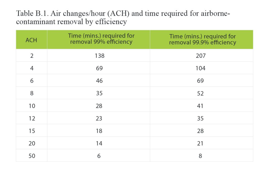
Jimmieson advises targeting a minimum of 5 air changes/hr (12 cycles) and bases his recommendation on CDC data (Table B.1). “Even with ten air changes an hour, i.e. every 6 minutes, it’s still going to take half an hour to get rid of any traces of an aerosol in the room, so air change rates need to be relatively high,” he explains.
The choice of filter matters when trying to arrest droplets containing small contaminants like viruses. ASHRAE recommends a minimum MERV-13 grade or better for commercial buildings. MERV-13 through 16 can achieve a 95-99% average removal efficiency for particles from 0.3 to 1.0 μm.
High Efficiency Particulate Air (HEPA) filters have an even higher performance, capturing 99.97% of particles with a size of 0.3 μm. However, their superior efficiency creates more pressure drop in your system, which will reduce airflow rates and therefore system performance.
CAVEAT Pressure drops from upgrading filters can have a significant impact on your HVAC system. In fact, most managers and owners will find it too difficult or impossible to retrofit their HVAC systems with HEPA filters without a costly or significant redesign. This hurdle is why ASHRAE recommends using portable systems with HEPA filters. Also, higher grade filters are costly and single use, so expect an uptick in operating costs.
Consider UV Germicidal Irradiation
Ultraviolet germicidal irradiation (UVGI) systems use short wavelength UV-C light to kill viruses and bacteria before they’re distributed by your ventilation system. UVGI systems for HVAC are usually mercury-based lamps or LEDs. As viruses pass through the HVAC system, the lamps “inactivate” any viruses captured by high efficiency filters or that move through the AHU.
UVGI lamps contribute to air sterilization, especially where outside air flow is restricted and/or dilution efforts are insufficient. However, UV-C does have limits. Jimmieson notes that one critical restriction that’s often overlooked is particle size. “By and large, a good rule of thumb is that if you’ve got a particle size that is bigger than 5 μm then you’re going to struggle to nuke that particle with UV light.”
It’s a fact that has implications for your filtration system, since low efficiency filters allow particles greater than 5 μm to pass through. If those larger particles are hosting viruses, then they may not be neutralized by your UVGI. “You really want to position the UVGI system downstream of a good quality filter to take the lumps out of the air,” Jimmieson recommends.